Fuse Selection Guide and Step
Walter is committed to giving you all the tools and support your need.
In addition to the resources, please select the Menu below for more product guide details.
Fuse Selection Guide
Factors to consider
1) Select the proper fuse size according to the available circuit space.
2) Select the proper fuse shape according to the mounting method of the circuit.
3) Select the proper fuse according to the product’s required
safety certification standards:
C-UL, VDE, SEMKO, PSE, CCC, KC, BSI.
4) Determine the proper fuse voltage rating according to the applied
voltage of the circuit.
5) Select the appropriate fuse current rating (In) according to the maximum normal
working current of the circuit.
- Considered the fuse decaying factors.
- Considered the derating of fuse based on the ambient temperature.
6) Consider the current pulse
- Calculate the circuit’s maximum current pulse I2t value.
- Calculate the required I2t value of fuse.
Time-lag fuse typically is recommended when distinctive current pulse is specified.
7) Select the fuse type.
8) Test run the selected fuse in the circuit/product.
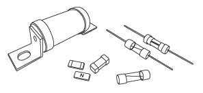
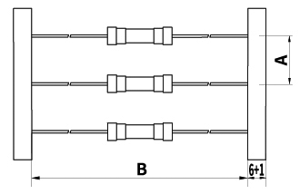
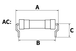
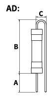
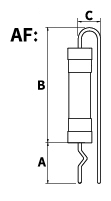
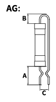
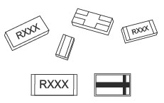
Taping & Forming
| Fuse Diameter | A(mm) | B(mm) |
|---|---|---|
| Φ3.0 | 5 | 52 |
| Φ36 | 5.6 | 52 |
| Φ4.6 | 10 | 52 |
| Φ5.2 | 10 | 52 |
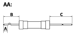
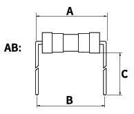
| FUSE SIZE Type |
Φ3.6(mm) | Φ4.6(mm) | Φ5.2(mm) | ||||||
|---|---|---|---|---|---|---|---|---|---|
| A | B | C | A | B | C | A | B | C | |
| AA | ≧2.5 | ≧6 | ≧5 | ≧3 | ≧6 | ≧5 | ≧3 | ≧6 | ≧5 |
| AB | ≧16 | ≧15.4 | ≧3.5 | ≧20.5 | ≧20 | ≧3.5 | ≧26 | ≧25 | ≧4 |
| AC | ≧16 | ≧11.5 | ≧7 | ≧20.5 | ≧16.5 | ≧7 | ≧26 | ≧21 | ≧6.5 |
| AD | ≧6 | ≧3.5 | ≧6.5 | ≧6 | ≧5 | ≧6.5 | ≧6 | ≧5 | ≧6.5 |
| AF | ≧6 | ≧3.5 | ≧5.5 | ≧6 | ≧5 | ≧5.5 | ≧6 | ≧5 | ≧5.5 |
| AG | ≧4 | ≧3.5 | ≧5.5 | ≧4 | ≧5 | ≧5.5 | ≧4 | ≧5 | ≧5.5 |
Step 1: Fuse Size & Shape
The fuse shape and size is determined by the available space within the circuit design and mounting requirements.Note: please refer to this catalog for fuse characteristics and physical specifications.
Step 2: Safety Agency Approvals
Select fuse according to the product’s required relevant safety certification approvals.Note: please refer to this catalog for fuse characteristics and physical specifications.
Step 3: Voltage Rating
Selected fuse should have a voltage rating greater than or equal to the applied circuit voltage, that is, the applied voltage must be smaller than or equal to rated voltage. For example, a 125V fuse can only be used in a circuit that is smaller than or equal to 125V, thus cannot be used in a 250V circuit. On the other hand, a 250V fuse can be used in the circuit that is smaller than or equal to 250V, thus includes the 125V range.
Step 4: Current Rating (In)
Current rating (In) = The maximum steady running of current / (Fuse decaying ratio* The applied ambient temperature derating)(1) Safety Decaying Factors
Test results may differ between laboratory testing and actual circuit application, due to contacting resistance from different types of fuse clip/holder used and circuit layouts. Please refer to safety decaying factor calculation guide listed below, to ensure proper fuse functioning within 25±5°C.
- UL standard fuse: current rating (In)= the maximum steady current of circuit / 0.75
- IEC standard fuse: current rating (In)= the maximum steady current of circuit / 0.90
- JIS standard fuse: current rating (In)= the maximum steady current of circuit / 0.85
(2)Ambient Temperature Derating
When working under 25±5°C, the temperature will not affect the rated current value of the fuse. However, when temperature exceeds 30°C, environmental condition dramatically influences the rated current value. Thus, thermal impacts are essential to be considered during fuse selection. Please refer to below chart:

Curve A: For FF, Fast-Acting and Time-Lag type fuses.
After calculating the current rating (In) considering above factors, the proper fuse current rating must be greater than or equal to the current rating (In).
Step 5: Pulse
The pulse refers to enduring large peaks at short time-interval (less than 10 ms) of instantaneous current (such as surge currents, start-up currents, inrush currents and transients). If the fuse is designated to endure inrush current without operating under normal circumstances, then pulse factors must be considered during the selection process.First, calculate the maximum pulse I2t based on the actual circuit
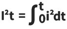
General reference chart provided below (see picture 2) indicates the closest matching pulse waveform and the formula to calculate I2t.

Secondly, consider the cycle endurance to select the pulse cycle frequency.
(See Picture 3)

Pulse cycle withstand capability:
100,000 pulses U=22% of Nominal melting I2t
10,000 pulses U=29% of Nominal melting I2t
1,000 pulses U=38% of Nominal melting I2t
100 pulses U=48% of Nominal melting I2t
Note: time-interval (10s) must be given between pulse events to adequately heat sink from the previous event.
Finally: consider the pulse cycle withstand capability (U) and the pulse I2t, to calculate I2t value of the fuse.
Average melting I2t of the fuse needed = Ratio ( Pulse I2t / U )
After calculating the average melting I2t value needed in the circuit and determining the thermal energy melting I2t value, select a fuse with thermal energy melting I2t value greater than or equal to the required average melting I2t value.
Step 6: Testing
After determining fuse specifications, samples must be tested in actual circuit to verify functional characteristics. This verification process includes testing under normal and defective working conditions, to ensure fuse can adequately protect the circuit.Working Function of CSR

- CSR is a type of current sensing resistor.件
- CSR transfers measured data to IC units to determine subsequent actions.
- CSR precision is extremely prominent.
- We offer high precision (△R<1%) and high power (P>2W) products.
Performance Characteristics
| Parameter | Conditions | Consent Standard |
|---|---|---|
| Short Time Over Load | Power=2.5*Pr ; T=25±2℃ ; t=5s | ± (1.0%+0.5mΩ) IEC60115-1 4.13 |
| High Temp. Exposure | T=+155±2℃; t=1,000hrs |
± (1.0%+0.5mΩ) IEC60115-1 4.25 |
| Low Temp. Load Life | T=-55±2℃; t=1,000hrs |
± (1.0%+0.5mΩ) IEC60115-1 4.25 |
| Moisture Load Life | Vtest=Vmax,ton=90min, toff=30min, T=60±2℃,RH=95%,1,000hrs(with above) |
± (2.0%+0.5mΩ) IEC60115-1 4.25 |
| Thermal Shock | [-55℃ 30min→ R.T. 3min→ +150℃ 30min→ R.T. 3min] by 100 Continuous Cycles |
± (1.0%+0.5mΩ) IEC60115-1 4.19 |
| Load Life at 70℃ | Vtest=Vmax; T=70±2℃; t=90min On t=30min Off; 1,000hrs |
± (2.0%+0.5mΩ) IEC60115-1 4.25 |
| Solderability | Dipped into Solder at 245±5℃ for 3±1s; | The covered area >95% IEC60115-1 4.17 |
| Resistance to Solder Heat | 20±1s at 275±5℃ | ± (1.0%+0.5mΩ) IEC60115-1 4.18 |
| Substrate Bending | Span Between Fulcrums: 90mm; Bend Width: 2mm; Test Board: Glass-Epoxy Board, Thickness=1.6mm by 10 continuous cycles |
± (0.5%+0.5mΩ) IEC60115-1 4.33 |
| Mechanical Shock | a=100G for 11ms, 5 Pulse | ± (0.5%+0.5mΩ) IEC60115-1 4.21 |
CSR Selection Guide
Step 1:
Select the required resistance values for the circuit.
Step 2:
Choose resistance value of the most accuracy and minimal error of resistance.
Step 3:
Confirm the regular maximum current that flows into the component from the circuit.
Step 4:
Calculate the required minimum rated power of the component.The selected value must be higher than the actual value.
Step 5:
Select size according to available space on the component.
Step 6:
Consider the thermal electromotive force (EMF)
For Example:
A design engineer requires Current Sensing Resistors (CSR) to protect the rear end of the power source, and 5 m Ω is required on the circuit design. In addition, the applied power management IC is highly sensitivity and allows low resistance error, thus resistance precision lower than 1% should be opted. Furthermore, its regular current-flow is approximately 15 A, so the applicable resistor should endure a power (P) = 1.125W. The power supply space allocation is limited, so smaller sizes such as 1206 should be selected. Finally, this particular system does consider the EMF effect, therefore, HTC1206C2W0R005F is selected.